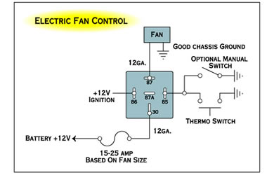
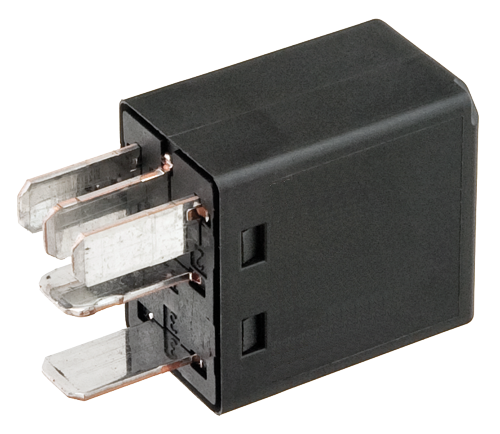
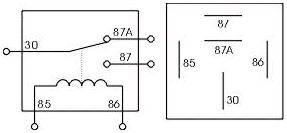
Automotive 5 Pin Relay Diagram. This diagram shows how another type of relay, the single pin/single throw (SPST) operates. Many automotive relays are similar in appearance and pin.
Here is a video on how you can test a Relay with or without a diagram.
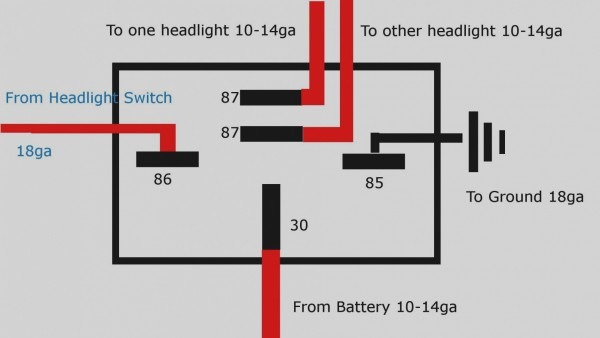
Identify the hot power wire (red wire in the diagram above) in the cord leading to the light bulb and make a cut.
Relay Case: How to Use Relays and Why You Need Them ...

Automotive relays relay harness 12V fuse relay switch harness
Automotive Relay Guide | 12 Volt Planet
Automotive Relay Guide | 12 Volt Planet

Waterproof 12V 5PIN Bosch 40A Relay Wire Harness Socket ...

Clap Switch Circuit Diagram Project | CircuitsTune
Narva Wiring Diagram
Automotive Relay Guide | 12 Volt Planet
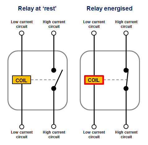
Automotive Relays | REUK.co.uk
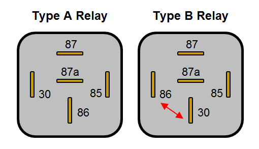
This is generally connected to the positive terminal of your signal source. Use an ohmmeter to find the pins with continuity, and some resistance that will indicate that you have found the coil that is the electromagnet to activate the relay. once you have found those two pins the remaining three will most likely be one Automotive relay Automotive Relay Guide A relay is essentially a switch that is operated electrically rather than mechanically.
